Autoclave Engineers
Fittings and Tubing
╣▄ĮėŅ^
Å─1945─Ļķ_╩╝Ż¼Autoclave Engineersķ_╩╝╔·«a(ch©Żn)Š▀ėą░▓╚½Īó┐╔┐┐▓┘ū„ąįĄ─Ė▀ē║ķyŽĄĮy(t©»ng)Ż¼╦³éā┐╔ęį▀mė├ė┌Ė„ĘN£žČ╚Īóē║┴”║═Łh(hu©ón)Š│ĀŅørĪŻĮ±╠ņŻ¼Autoclave EngineersęčĮø(j©®ng)░l(f©Ī)š╣│╔×ķĖ„ŅÉĖ▀ē║ąąśI(y©©)╠ß╣®┐╔┐┐Ą─Ė▀ē║ķyĪóĮėŅ^║═╣▄ūėĄ─╩└ĮńŅI(l©½ng)Ž╚š▀ĪŻ«a(ch©Żn)ŲĘąį─▄╩ŪAutoclave Engineersī”┐═æ¶Ą─│ąųZŻ¼AutoclaveĄ─ķyĪóĮėŅ^║═╣▄ūėØMūŃć└(y©ón)Ė±Ą─ś╦(bi©Īo)£╩(zh©│n)Ż¼╦³Ą─ē║┴”┐╔ęįÅ─0ĄĮ150,000 psi(10343 bar) Ż¼£žČ╚Å─ 0 ĄĮ 1200ĪŃF (650ĪŃC)ėą╔ŽŪ¦ĘNūā╗»ĪŻø]ėąäeĄ─╣żÅS─▄▒╚Autoclave Engineersį┌Ė▀ē║ę¬Ū¾ĘĮ├µū÷Ą├Ė³║├Ż¼ę▓ø]ėąäeĄ─╣żÅS─▄▒╚Autoclave Engineersū÷Ą─ŽĄĮy(t©»ng)Ė³┐╔┐┐║═Š▀ėąäō(chu©żng)ą┬Ą─╠žąįĪŻAutoclave EngineersĄ─«a(ch©Żn)ŲĘ×ķØMūŃ┐═æ¶Ą─Ė„ĘNąĶŪ¾Č°įO(sh©©)ėŗ(j©¼)Ż¼▓óŪęŠ▀ėąŲĘ┘|(zh©¼)Ė▀Ż¼Į╗žø£╩(zh©│n)Ģr(sh©¬)Ż¼ār(ji©ż)Ė±▀m«ö(d©Īng)?sh©┤)─╠ž³c(di©Żn)ĪŻ
Autoclave Fittings and Tubing
Low Pressure Fittings and Tubing:
Pressures to 15,000 psi (1034 bar)
.Elbows, Tees, Crosses, Straight and Bulkhead Couplings.
.Tubing
.Check Valves & Filters
Medium Pressure Fittings and Tubing:
Pressures to 20,000 psi (1379 bar)
.Elbows, Tees, Crosses, Straight, Union, and Bulkhead Couplings.
.Tubing and Nipples
.Check Valves & Filters
.Anti-Vibration Collet and Gland Assembly
High Pressure Fittings and Tubing:
Pressures to 150,000 psi (10347 bar)
.Elbows, Tees, Crosses, Straight, Union, and Bulkhead Couplings.
.Tubing and Nipples
.Check Valves & Filters
.Anti-Vibration Collet and Gland Assembly
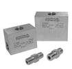
Fittings, Tubing & Nipples
High Pressure
Pressures to 150,000 psi (10342 bar)
Since 1945 Autoclave Engineers has designed and built premium quality valves, fittings and tubing. This commitment to engineering and manufacturing excellence has earned Autoclave a reputation for reliable, efficient product performance. Autoclave Engineers has long been established as the world leader in high pressure fluid handling components for the chemical/petrochemical, research, and oil and gas, waterjet, and waterblast industries.
High Pressure Fittings, Tubing and Nipples Features:
.
Coned-and-Threaded Connection.
.
Available sizes are 1/4, 5/16, 3/8, 9/16, and 1Ī▒.
.
Fittings and tubing manufactured from cold worked
stainless steel.
.
Operating Temperatures from -423ĪŃF (-252ĪŃC) to 1200ĪŃF (649ĪŃC).
.
Anti-vibration connection components available.
.
Ultra-high pressure components.
.
Autofrettaged tubing.
.
High pressure high cycle tubing.
The high and ulta-high pressure series uses AutoclaveĪ»s high pressure connector. This coned-and-threaded connection provides dependable performance in gas or liquid service.
www.autoclaveengineers.com
High Pressure Fittings
Pressures to 150,000 psi (10342 bar)
Autoclave Engineers high pressure fittings Series F and SF are the industry standard for pressures to 150,000 psi (10342 bar). Utilizing Autoclave Engineers high pressure coned-and-threaded connections, these fittings are correlated with Series 30VM, 30SC, 40VM, 60VM, 100V, and 150V valves and Autoclave Engineers high pressure tubing.
Connection Components
All Autoclave Engineers valves and fittings are supplied complete with appropriate glands and collars. To order these components separately, use order numbers listed. When using plug, collar is not required.
Gland PlugCollar
AGL ( )
AP ( )ACL ( )
Add tube size ( ) 1/4Ī▒ - 40 Example: 1/4Ī▒ Gland - AGL (40) To ensure proper fit use Autoclave Engineers tubing.
5/16Ī▒ - 50 3/8Ī▒ - 60 9/16Ī▒ - 90 Note: Special material glands maybe supplied with four flats in place of standard hex.
1Ī▒ - 160
Connection Type Gland Collar Plug Connection Components (Industry Standard)
F250C F375C F562C AGL( ) ACL( ) AP( ) Autoclave EngineerĪ»s high pressure fittings 1/4, 3/8 and 9/16 connection components to 60,000 psi (4137 bar). For use with 30VM, 40VM, 60VM valves and fittings.
SF1000CX43 CGLX160 CCLX160 43CPX160 Autoclave EngineerĪ»s high pressure 1Ī▒ connection components to 43,000 psi (2965 bar) for use with 30SC, 43Y valves, and fittings.
F312C150 CGL50 CCL50 CP50 Autoclave EngineerĪ»s ultra high pressure 5/16 connection components to 150,000 psi ( 10342 bar) for use with 100V and 150V valve and fittings.
Elbow
CL4400 F250C 1/4 60,000 0.094 1.00 1.50 0.50 0.63 0.62 0.88 0.75
(6.35) (4136.79) (2.39) (25.40) (38.10) (12.70) (15.88) (15.75) (22.35) (19.05)
CL5500 F312C150 5/16 150,000 0.062 2.12 3.00 0.52 0.75 1.50 1.50 1.38
(7.94) (10341.97) (1.57) (53.85) (76.20) (13.21) (19.05) (38.10) (38.10) (35.05) See Figure 1
CL6600 F375C 3/8 (9.53) 60,000 (4136.79) 0.125 (3.18) 1.50 (38.10) 2.00 (50.80) 0.53 (13.46) 0.81 (20.62) 1.00 (25.40) 1.25 (31.75) 1.00 (25.40)
CL9900 F562C 9/16 60,000 0.188 1.88 2.62 0.81 1.19 1.12 1.88 1.50
(14.29) (4136.79) (4.78) (47.75) (66.55) (20.57) (30.23) (28.45) (47.75) (38.10)
40CL9900 F562C40 9/16 40,000 0.250 1.88 2.62 0.81 1.19 1.12 1.88 1.50
(14.29) (2757.86) (6.35) (47.775) (66.55) (20.57) (30.23) (28.45) (47.75) (38.10)
43CLX16 SF1000CX43 1 43,000 0.438 3.00 4.12 0.72 1.38 2.06 2.06 1.75
(25.40) (2964.70) (11.13) (76.20) (104.65) (18.29) (35.05) (52.32) (52.32) (44.45)
Tee
CT4440 F250C 1/4 60,000 0.094 1.25 2.00 0.50 0.63 0.88 1.00 1.00
(6.35) (4136.79) (2.39) (31.75) (50.80) (12.70) (15.88) (22.35) (25.40) (25.40)
CT5550 F312C150 5/16 150,000 0.062 2.12 3.00 0.52 0.75 1.50 1.50 1.38
(7.94) (10341.97) (1.57) (53.85) (76.20) (13.21) (19.05) (38.10) (38.10) (35.05) See Figure 2
CT6660 F375C 3/8 (9.53) 60,000 (4136.79) 0.125 (3.18) 1.56 (39.62) 2.00 (50.80) 0.53 (13.46) 0.81 (20.62) 1.06 (26.92) 1.00 (25.40) 1.00 (25.40)
CT9990 F562C 9/16 60,000 0.188 2.12 2.62 0.81 1.19 1.38 1.31 1.50
(14.29) (4136.79) (4.78) (53.85) (66.55) (20.57) (30.23) (35.05) (33.27) (38.10)
40CT9990 F562C40 9/16 40,000 0.250 2.12 2.62 0.81 1.19 1.38 1.31 1.50
(14.29) (2757.86) (6.35) (53.85) (66.55) (20.57) (30.23) (35.05) (33.27) (38.10)
43CTX16 SF1000CX43 1 43,000 0.438 3.00 4.12 0.72 1.38 2.06 2.06 1.75
(25.40) (2964.70) (11.13) (76.20) (104.65) (18.29) (35.05) (52.32) (52.32) (44.45)
Cross
CX4444 F250C 1/4 60,000 0.094 1.25 2.00 0.50 0.63 0.62 1.00 1.00
(6.35) (4136.79) (2.39) (31.75) (50.80) (12.70) (15.88) (15.75) (25.40) (25.40)
CX5555 F312C150 5/16 150,000 0.062 3.00 3.00 0.52 0.75 1.50 1.50 1.38
(7.94) (10341.97) (1.57) (76.20) (76.20) (13.21) (19.05) (38.10) (38.10) (35.05) See Figure 3
CX6666 F375C 3/8 (9.53) 60,000 (4136.79) 0.125 (3.18) 2.12 (53.85) 2.00 (50.80) 0.53 (13.46) 0.81 (20.62) 1.06 (26.92) 1.00 (25.40) 1.00 (25.40)
CX9999 F562C 9/16 60,000 0.188 2.75 2.62 0.81 1.19 1.38 1.31 1.50
(14.29) (4136.79) (4.78) (69.85) (66.55) (20.57) (30.23) (35.05) (33.27) (38.10)
40CX9999 F562C40 9/16 40,000 0.250 2.75 2.62 0.81 1.19 1.38 1.31 1.50
(14.29) (2757.86) (6.35) (69.85) (66.55) (20.57) (30.23) (35.05) (33.27) (38.10)
43CXX16 SF1000CX43 1 43,000 0.438 4.12 4.12 0.72 1.38 2.06 2.06 1.75
(25.40) (2964.70) (11.13) (104.65) (104.65) (18.29) (35.05) (52.32) (52.32) (44.45)
*Maximum pressure rating is based on the lowest rating of any component.
Actual working pressure may be determined by tubing pressure rating, if lower.
All dimensions for reference only and subject to change.
For prompt service, Autoclave stocks select products. Consult your local representative.
Figure 1
E
A
D HEX
F
C
B
Elbow
Note: Fittings such as 45ĪŃ elbows, reducer elbows, and reducer 45ĪŃ elbows are available upon request.
For mounting hole option add suffix PM to catalog number, consult factory for mounting hole dimensions.
Contact your local sales representative for additional information.
Straight Coupling/Union Coupling
60F4433 F250C 1/4 60,000 0.094 0.75 1.38 0.50 0.63 Straight See Figure 4
60UF4433 (6.35) (4136.79) (2.39) (19.05) (35.05) (12.70) (15.88) Union
150F5533 F312C150 5/16 150,000 0.062 1.12 2.62 0.52 0.75 Straight
150UF5533 (7.94) (10341.97) (1.57) (28.52) (66.55) (13.21) (19.05) Union
60F6633 F375C 3/8 60,000 0.125 1.00 1.75 0.53 0.81 Straight
60UF6633 (9.53) (4136.79) (3.18) (25.40) (44.45) (13.46) (20.62) Union
60F9933 F562C 9/16 60,000 0.188 1.38 2.19 0.81 1.19 Straight
60UF9933 (14.29) (4136.79) (4.78) (35.05) (55.63) (20.57) (30.15) Union
40F9933 F562C40 9/16 40,000 0.250 1.38 2.19 0.81 1.19 Straight
40UF9933 (14.29) (2757.86) (6.35) (35.05) (55.63) (20.57) (30.15) Union
43FX16 SF1000CX43 1 43,000 0.438 1.75 3.50 0.72 1.38 Straight
43UFX16 (25.40) (2964.70) (11.13) (44.45) (88.90) (18.29) (35.05) Union
Bulkhead Coupling
60BF4433 F250C 1/4 60,000 0.094 0.094 1.88 0.50 0.63 0.50 1.00 0.38
(6.35) (4136.79) (2.39) (23.88) (47.75) (12.70) (15.88) (12.70) (25.40) (9.65)
150BF5533 F312C150 5/16 150,000 0.062 2.12 3.25 0.52 0.75 1.38 2.00 0.38
(7.94) (10341.97) (1.57) (53.85) (82.55) (13.21) (19.05) (35.05) (50.80) (9.65) See Figure 5
60BF6633 F375C 3/8 (9.53) 60,000 (4136.79) 0.125 (3.18) 1.12 (28.45) 2.38 (60.45) 0.53 (13.46) 0.81 (20.62) 0.78 (19.81) 1.38 (35.05) 0.38 (9.65)
60BF9933 F562C 9/16 60,000 0.188 1.69 2.75 0.81 1.19 1.00 1.88 0.38
(14.29) (4136.79) (4.78) (42.93) (69.85) (20.57) (30.23) (25.40) (47.75) (9.65)
40BF9933 F562C40 9/16 40,000 0.250 1.69 2.75 0.81 1.19 1.00 1.88 0.38
(14.29) (2757.86) (6.35) (42.93) (69.85) (20.57) (30.23) (25.40) (47.75) (9.65)
43BFX16 SF1000CX43 1Ī▒ 43,000 0.438 1.75 3.50 0.72 1.38 1.50 2.13 0.50
(25.40) (2964.70) (11.13) (44.45) (88.90) (18.29) (35.05) (38.10) (54.10) (12.70)
*Maximum pressure rating is based on the lowest rating of any component.
Actual working pressure may be determined by tubing pressure rating, if lower.
All dimensions for reference only and subject to change.
For prompt service, Autoclave stocks select products. Consult your local representative.
Union Couplings are designed with a removable seat insert allowing disassembly and tubing removal without the necessity of loosening other items in a line.
High Pressure Tubing
Pressures to 150,000 psi (10342 bar)
Autoclave Engineers offers a complete selection of austenetic, cold drawn stainless steel tubing designed to match the performance standards of Autoclave valves and fittings. Autoclave high pressure tubing is manufactured specifically for high pressure applications requiring both strength and corrosion resistance. The tubing is furnished in random lengths between 20 feet (6 meters) and 27 feet (8.2 meters). The average is 24 feet (7.3 meters). High pressure tubing is available in five sizes and a variety of materials. Special longer lengths are available. Consult factory.
Inspection and Testing
Autoclave EngineerĪ»s high pressure tubing is inspected to assure freedom from seams, laps, fissures or other flaws, as well as carburization or intergranular carbide precipitation. The outside and inside diameters of the tubing are controlled within close tolerences. Sample pieces of tubing for each lot are tested to confirm mechanical properties. Hydrostatic testing is also performed on a statistical basis and is conducted at the working pressure of the tube. Autoclave will perform 100% hydrostatic
testing at additional cost if desired.
Special Materials Tubing Tolerance
In addition to the type 316 and 304 stainless steel tubing listed Nominal Tubing Size Tolerance/Outside Diameter
in this section, Autoclave has limited stock of hard-to-obtain inches (mm) inches (mm)
shorter lengths of the following tubing materials in some
sizes: 1/4 (6.35) .248/.243 (6.30/6.17)
Monel 400*, Inconel 600*, Titanium Grade 2*, Nickel 200*, 5/16 (7.94) .310/.306 (7.87/7.77)
Hastelloy C276* -(* Trademark names) 3/8 (9.53) .370/.365 (9.40/9.27)
Please consult factory for stock availabilty. 9/16 (14.29) 1 (25.40) .557/.552 (14.15/14.02) .995/.990 (25.27/25.14)
Catalog Tube Fits Tube Size Inches (mm) Flow Working Pressure psi (bar)*
Number Material Connection Outside Inside Wall Area -325 to 100ĪŃF 200ĪŃF 400ĪŃF 600ĪŃF 800ĪŃF
Type Diameter Diameter Thickness in.2 (mm2) -198 to - 37.8ĪŃC 93ĪŃC 204ĪŃC 316ĪŃC 427ĪŃC
MS15-081 316SS 60,000 60,000 57,750 54,250 50,700
(4136.79) (4136.79) (3981.66) (3740.35) (3495.59)
MS15-182 304SS F250C 1/4 0.083 0.083 0005 60,000 56,800 51,650 50,700 48,450
(6.35) (2.11) (2.11) (3.23) (4136.79) (3916.16) (3561.09) (3495.59) (3340.46)
MS15-202 Stainless 95,000 95,000 91,400 85,850 80,200
(6549.92) (6549.92) (6301.71) (5919.06) (5529.51)
MS15-082 316SS F312C150 5/16 0.062 0.125 0.033 150,000 150,000 144,400 136,350 126,750
(7.94) (1.57) (3.18) (1.94) (10341.97) (10341.97) (9955.87) (9400.85) (8738.97)
MS15-087 316SS 60,000 60,000 57,750 54,250 50,700
(4136.79) (4136.79) (3981.66) (3740.35) (3495.59)
MS15-183 304SS F375C 3/8 0.125 0.125 0.012 60,000 56,800 51,650 50,700 48,450
(9.53) (3.18) (3.18) (7.74) (4136.79) (3916.16) (3561.09) (3495.59) (3340.46)
MS15-201 Stainless 95,000 95,000 91,400 85,850 80,200
MS15-083 316SS (6549.92) 60,000 (6549.92) 60,000 (6301.71) 57,750 (5919.06) 54,250 (5529.51) 50,700
(4136.79) (4136.79) (3981.66) (3740.35) (3495.59)
MS15-185 304SS F562C 9/16 0.188 0.187 0.028 60,000 56,800 51,650 50,700 48,450
(14.29) (4.78) (4.75) (18.06) (4136.79) (3916.16) (3561.09) (3495.59) (3340.46)
MS15-203 Stainles 95,000 95,000 91,000 85,850 80,200
MS15-090 316SS (6549.92) 40,000 (6549.92) 40,000 (6301.71) 38,500 (5919.06) 36,100 (5529.51) 33,800
F562C40 9/16 0.250 0.156 0.048 (2757.86) (2757.86) (2654.44) (2488.96) (2330.39)
MS15-189 304SS (14.29) (6.35) (3.96) (30.97) 40,000 36,800 31,650 30,700 28,450
(2757.86) (2537.23) (2182.16) (2116.66) (1961.53)
MS15-204 Stainless F562C40-312 9/16 0.312 0.125 0.076 40,000 40,000 38,500 36,100 33,800
(14.29) (7.92) (3.18) (49.03) (2757.86) (2757.86) (2654.44) (2488.97) (2330.39)
MS15-199 304SS SF1000CX43 1 0.438 0.281 0.151 43,000 40,600 36,900 36,300 34,700
(25.40) (11.13) (7.14) (97.42) (2964.70) (2799.23) (2544.13) (2502.76) (2392.44)
Note:
1.
Autofrettaged tubing available (see technical Information section: Pressure *Maximum pressure rating is based on the lowest rating of any component. Cycling for Autofrettage information) Actual working pressure may be determined by tubing pressure rating, if lower.
2.
For HighPressure, High Cycle (HPHC) tubing, MS15-201, MS15-202, MS15-203, All dimensions for reference only and subject to change.
and MS15-204 are available. (See Technical Information section: Pressure Cycling For prompt service, Autoclave stocks select products. Consult your local representative.
for additional information)
High Pressure Coned-and-Threaded Nipples
Pressures to 150,000 psi (10342 bar)
For rapid system make-up, Autoclave Engineers supplies precut, coned-and-threaded nipples in various sizes and lengths for Autoclave high pressure valves and fittings.
Special lengths
In addition to the standard lengths listed in the table below, nipples are available in any custom length. Consult factory.
Materials**
Catalog numbers in table refer to Type 316 Stainless steel.
Material in table is 316 Stainless steel
Catalog Number Fits Connection Type Tube Size inches (mm) Working* Pressure at 100ĪŃF (37.8ĪŃC) psi (bar)
Nipple Length In (mm)
2.75Ī▒ (69.85) 3.00Ī▒(76.20) 4.00Ī▒ (101.60) 6.00Ī▒ (152.40) 8.00Ī▒ (203.20) 10.00Ī▒ (254.00) 12.00Ī▒ (304.80)
O.D. I.D.
CN4402 CN4403 CN4404 CN4406 CN4408 CN44010 CN44012 F250C 1/4 (6.35) 0.083 (2.11) 60,000 (4136.79)
CN6603-316 CN6604-316 CN6606-316 CN6608-316 CN66010-316 CN66012-316 F375C 3/8 (9.53) 0.125 (3.18) 60,000 (4136.79)
CN9904-316 CN9906-316 CN9908-316 CN99010-316 CN99012-316 F562C 9/16 (14.29) 0.188 (4.78) 60,000 (4136.79)
CN5504-316 CN5506-316 CN5508-316 CN55010-316 CN55012-316 F312C150 5/16 (7.94) 0.062 (1.57) 150,000 (10341.97)
Material in table is 304 Stainless steel
40CN9904-304 40CN9906-304 40CN9908-304 40CN99010-304 40CN99012-304 F562C40 9/16 (14.29) 0.250 (6.35) 40,000 (2757.86)
43CNX1606 43CNX1608 43CNX16010 43CNX16012 SF1000CX43 1 (25.40) 0.438 (12.40) 43,000 (2964.70)
Note:
See High pressure tubing section for pressure ratings at various temperatures.
**Type 304 stainless steel nipples available.
*Maximum pressure rating is based on the lowest rating of any component.
Actual working pressure may be determined by tubing pressure rating, if lower.
All dimensions for reference only and subject to change.
For prompt service, Autoclave stocks select products. Consult your local representative.
High Pressure Check Valves
Pressures to 60,000 psi (4137 bar)
O-Ring Check Valves
Ball Check Valves
Ball Type Excess Flow Valves
Provides unidirectional flow and tight shut-off for liquids and gas with high reliability. When differential drops below cracking pressure*, valve shuts off. (Not for use as relief valve.)
Materials: Body, cover, poppet: 316 Stainless Steel, Cover gland: Stainless Steel, Spring: 300 Series Stainless Steel, Standard O-ring: Viton, for operation to 500ĪŃ F (260ĪŃC). Buna-N or Teflon available for 250ĪŃF (121ĪŃC) or 400ĪŃF (204ĪŃC) respectively; specify when ordering.
*Cracking Pressure: 20 psi (1.38 bar) Ī└30%. Springs for higher cracking pressures (up to 100 psi (6.89 bar)) available on special order for O-ring style check valves only.
Prevents reverse flow where leak-tight shut-off is not mandatory. When differential drops below cracking pressure, valve closes. With all-metal components, valve can be used up to 1200ĪŃF (649ĪŃC). See Technical Information section for connection temperature limitations. (Not for use as a relief valve.)
Ball is cradled in floating poppet to assure positive, in-line seating without Ī░chatterĪ▒. Poppet is designed essentially for axial flow with minimum pressure drop.
Materials: Body, cover, poppet: 316 Stainless Steel, Cover gland: Stainless Steel, Ball, Spring: 300 Series Stainless Steel
Protects pressure gauges and pressure instrumentation from
surges in flow or sudden venting in the event of line failure. Materials: Body, cover, sleeve: Type 316 Stainless Steel, Ball: 300 Series Stainless Steel, Cover gland: stainless steel.
Vertical Installation: Since this type of check valve employs a non-spring loaded ball, valve MUST be installed in VERTICAL position with arrow on valve body pointing UP. (cover gland up).
Resetting Valve: Equalize the pressure across the ball. The ball will drop and reset automatically.
CAUTION: While testing has shown O-Rings to provide satisfactory service life, both cyclic and shelf life may vary widely with differing service conditions, properties of reactants, pressure and temperature cycling and age of the O-ring. FREQUENT INSPECTIONS SHOULD BE MADE to detect any deterioration, and O-rings replaced as required.
NOTE: For optional material see Needle Valve Options section.
High Pressure Check Valves
Catalog Number Fits Connection Type Pressure Rating psi (bar)* Orifice inches (mm) Rated Cv Dimensions - inches (mm)
A B C D Typical Hex
O-Ring Check Valves
CKO4400 F250C 60,000 0.094 0.15 3.38 2.50 0.50 0.63 1.18
(4136.79) (2.39) (85.85) (63.50) (12.70) (16.00) (29.97)
CKO6600 F375C 60,000 0.125 0.28 3.75 2.62 0.53 0.75 1.18
(4136.79) (3.18) (95.25) (66.55) (13.46) (19.05) (29.97) See
CKO9900 F562C 60,000 0.187 0.63 4.62 3.38 0.81 1.12 1.50
(4136.79) (4.75) (117.35) (85.85) (20.57) (28.45) (38.10) Figure 1
40CKO9900 F562C40 40,000 0.250 0.78 4.64 3.38 0.72 1.19 1.50
(2757.85) (6.35) (117.86) (85.73) (18.29) (30.23) (38.10)
443CXB16 SF1000CX43 43,000 0.438 4.3 6.54 5.63 .72 1.38 1.88
(2964.70) (11.13) (166.11) (143.00) (18.29) (35.05) (47.76)
Ball Check Valves
CB4400 F250C 60,000 0.094 0.15 3.38 2.50 0.50 0.63 1.18
(4136.79) (2.39) (85.85) (63.50) (12.70) (16.00) (29.97)
CB6600 F375C 60,000 0.125 0.28 3.75 2.62 0.53 0.75 1.18
(4136.79) (3.18) (95.25) (66.55) (13.46) (19.05) (29.97) See Figure 1
CB9900 F562C 60,000 (4136.79) 0.187 (4.75) 0.63 4.62 (117.35) 3.38 (85.85) 0.81 (20.57) 1.12 (28.45) 1.50 (38.10)
43CXB16 SF1000CX43 43,000 0.438 4.3 6.54 5.63 .72 1.38 1.88
(2964.70) (11.13) (166.11) (143.00) (18.29) (35.05) (47.76)
Ball Type Excess Flow Valves
CK4402 F250C 60,000 0.094 3.38 2.50 0.50 0.63 1.18
(4136.79) (2.39) (85.85) (63.50) (12.70) (16.00) (29.97) See Figure 1
CK6602 F375C 60,000 (4136.79) 0.125 (3.18) 3.75 (95.25) 2.62 (66.55) 0.53 (13.46) 0.75 (19.05) 1.18 (29.97)
CK9902 F562C 60,000 0.187 4.62 3.38 0.81 1.12 1.50
(4136.79) (4.75) (117.35) (85.85) (20.57) (28.45) (38.10)
*Maximum pressure rating is based on the lowest rating of any component.
Actual working pressure may be determined by tubing pressure rating, if lower.
All dimensions for reference only and subject to change.
For prompt service, Autoclave stocks select products. Consult your local representative.
High Pressure Line Filters
Pressures to 60,000 psi (4137 bar)
Dual-Disc Line Filters
Cup-Type Line Filters
Autoclave Engineers Dual-Disc Line Filters are utilized in
numerous industrial, chemical processing, aerospace,
nuclear and other applications. With the dual-disc design,
large contaminant particles are trapped by the upstream filter
element before they can reach and clog the smaller micron-
size downstream element. Filter elements can be easily
replaced.
Materials: Body: cold-worked Type 316 Stainless Steel, Filter
Elements: 300 Series Stainless Steel.
Filter Elements: Downstream/upstream micron size 35/65 is
standard. 5/10 or 10/35 also available when specified. Other
element combinations available on special order.
Autoclave Engineers High Flow Cup-Type Line Filters are
recommended in high pressure systems requiring both high
flow rates and maximum filter surface area. Widely used in
the industrial and chemical processing fields, the cup design
offers as much as six times the effective filter area as
compared to disc-type units. In addition, the filter elements
can be quickly and easily replaced.
Materials: Body and Cover: cold-worked Type 316 Stainless
Steel. Filter Element: 300 Series Stainless Steel.
Filter Elements: 300 Series Stainless Steel sintered cup.
Standard elements available in choice of 5, 35 or 65 micron
sizes.
NOTE: All filters furnished complete with connection components unless specified without. All dimensions for reference only and subject to change.
Autoclave Engineers disc and cup type filters are designed to filter small amounts of process particles. It is recommended that all fluids are thoroughly cleaned prior to entering the higher pressure system.
For optional materials, see Needle Valve Options section
NOTE 1: Special material filters may be supplied with four flats in place of standard hex.
NOTE 2: Pressure differential not to exceed 1,000 psi (69 bar) in a flowing condition.
Catalog Number Pressure Rating psi (bar)* Orifice inches (mm) Micron Size** Connection Size and Type Effective Filter Element Area in.2 (mm2) Dimensions - inches (mm)
A B C D Typical Hex
Dual-Disc Line Filters
CLF4400 60,000 0.094 35/65 F250C 0.07 (45.16) 4.75 (20.65) 3.00 (76.20) 0.50 (12.70) .63 (16.00) 1.12 (28.45)
CLF4400-5/10 (4136.79) (2.39) 5/10
CLF4400-10/35 10/35
CLF6600 60,000 0.125 35/65 F375C 0.07 (45.16) 5.12 (130.16) 3.00 (76.20) 0.53 (13.46) .75 (19.05) 1.12 (28.45)
CLF6600-5/10 (4136.79) (3.18) 5/10
CLF6600-10/35 10/35
CLF9900 60,000 0.187 35/65 F562C 0.15 (96.77) 5.81 (147.57) 3.38 (85.85) 0.81 (20.58) 1.12 (28.45) 1.38 (35.05)
CLF9900-5/10 (4136.79) (4.75) 5/10
CLF9900-10/35 10/35
Cup-Type Line Filters
CF4-5 60,000 0.094 5 F250C 1.29 (832.26) 4.19 (106.42) 3.38 (85.85) 0.50 (12.70) .63 (16.00) 1.38 (35.05)
CF4-35 (4136.79) (2.39) 35
CF4-65 65
CF6-5 60,000 0.125 5 F375C 1.29 (832.26) 4.62 (117.35) 3.62 (91.94) 0.53 (13.46) .75 (19.05) 1.38 (35.05
CF6-35 (4136.79) (3.18) 35
CF6-65 65
CF9-5 60,000 0.187 5 F562C 1.29 (832.26) 5.25 (133.35) 4.06 (103.12) 0.81 (20.58) 1.12 (28.45) 1.50 (38.10)
CF9-35 (4136.79) (4.75) 35
CF9-65 65
Note:
**Other micron sizes available on special order. Change last digits of the catalog number accordingly.
For optional materials, see Needle Valve Options section.
*Maximum pressure rating is based on the lowest rating of any component.
Actual working pressure may be determined by tubing pressure rating, if lower.
All dimensions for reference only and subject to change.
For prompt service, Autoclave stocks select products. Consult your local representative.
Dual-Disc Line Filters
Cup-Type Line Filters
High Anti-Vibration Collet Gland Assembly
Pressures to 150,000 psi (10342 bar)
Series KCGL Sizes to 9/16Ī▒ (14.29 mm)
For extreme conditions of vibration and/or shock in tubing systems, such as locating valve or fitting on an unsupported line near a compressor, Autoclave coned-and-threaded connections are offered with the Anti-Vibration Collet Gland Assemblies. Completely interchangeable with standard Autoclave high pressure connections, the Collet Gland Assemblies provide equally effective pressure handling capability.
In standard connection systems, the bending stresses on the threaded area of the tubing imposed by excessive vibration or movement may cause premature fatigue failure of the tubing at the back of the thread. By moving the stress concentration back to the unthreaded part of the tubing and providing a wedge-type gripping action, the Autocalve Engineers anti-vibration collet gland assembly strengthens the entire structure. With stress concentration reduced and overall stress level maintained well below the endurance limit of the material, the result is virtually unlimited vibrational fatigue life.
A less complex and more economical design than other vibration-resistant connections, the Collet Gland Assembly utilizes the same coned-and-threaded features of Autoclave high pressure connections. In Series KCGL the gland nut is recessed to accommodate a tapered, slotted collet that grips the tubing at a point behind the threaded area of the tubing.The design provides a slight difference in angles between the collet and the corresponding taper of the gland nut. As the nut is tightened, it acts to wedge the tapered end of the collet into a gripping engagement with the tubing and, at the same time, forces the collar and tubing assembly into line contact with the connection seat.
Note: Special material assemblies may be supplied with four flats in place of standard hex.
Catalog
Number
Part
KCGL40-316
Complete assembly
KCL40-316 Slotted collet
KGL40-316 Gland nut
Outside Diameter Tubing Size in. (mm)
1/4
(6.35)
Dimensions - inches (mm)
A B Hex
0.50 0.81 0.62
(12.70) (20.58) (15.75)
KCGL60-316
Complete assembly
KCL60-316
Slotted collet
3/8
0.62
1.12
0.81
KGL60-316
Gland nut
(9.53)
(15.75)
(28.45)
(20.58)
KCGL90-316
Complete assembly
KCL90-316
Slotted collet
9/16
1.00
1.50
1.19
KGL90-316
Gland nut
(14.29)
(25.40)
(38.10)
(30.23)
All dimensions for reference only and subject to change.
For prompt service, Autoclave stocks select products. Consult your local representative.
Series KCBGLX -Sizes to 1Ī▒ (25.40 mm) Series KCBGL -Sizes to 5/16Ī▒ (7.94 mm)
For extreme conditions of vibration and/or shock in tubing systems, such as locating a valve or fitting on an unsupported line near a compressor, Autoclave coned-andthreaded connections are offered with the Anti-Vibration Collet Gland Assemblies. A less complex and more economical design than other vibration-resistant connections, the collet gland assembly utilizes the same coned-and -threaded features of Autoclave high pressure connections.
Series KCBGLX and KCBGL extends the gland nut to provide room for the tapered, slotted collet and collet nut. The design provides a slight difference in angles between the collet and the corresponding taper of the gland nut. As the nut is tightned, it acts to wedge the tapered end of the collet into a gripping engagement with the tubing.
Catalog Number Part Outside Diameter Tubing Size in. (mm) Dimensions - inches (mm) Series KCBGLX -43,000 psi (2965 bar) Series KCBGL -150,000 psi (10342 bar) Standard Autoclave Engineers collar not included in complete assembly A B Hex
A B Hex
KCBGLX160-316MC Complete assembly 1.0 (25.40) 1.69 (42.92) 2.38 (60.45) 1.50 (38.10)
KCBLX160-316MC Collet body
KCCLX160-316MC Slotted collet
KGLX160-316MC Gland nut
KCBGL50-316MC Complete assembly .312 (7.94) 1.38 (34.92) 1.88 (47.62) .75 (19.05)
KCBL50-316MC Collet body
KCCL50-316MC Slotted collet
KGL50-316MC Gland nut
Fittings and Tubing
Low Pressure
Pressures to 15,000 psi (1034 bar)
Since 1945 Autoclave Engineers has designed and built premium quality valves, fittings and tubing. This commitment to engineering and manufacturing excellence has earned Autoclave a reputation for reliable, efficient product performance. Autoclave Engineers has long been established as the world leader in high pressure fluid handling components for the chemical/petrochemical, research, and oil and gas industries.
Low Pressure Fittings and Tubing Features:
.
Single-ferrule compression sleeve.
.
Fast easy make-up of connection.
.
Available sizes are 1/16Ī▒, 1/8Ī▒, 1/4Ī▒, 3/8Ī▒, & 1/2Ī▒.
.
Fittings manufactured from cold worked stainless steel.
.
Tubing is manufactured from annealed stainless steel.
.
All items available in special materials.
.
Operating temperatures from 0ĪŃF (-17.8ĪŃC) to 650ĪŃF (343ĪŃC).
The Low Pressure Series uses AutoclaveĪ»s SpeedBite connection. This single-ferrule compression sleeve connection delivers fast, easy make-up and reliable bubble-tight performance, in liquid or gas service.
www.autoclaveengineers.com
Fittings and Tubing -Low Pressure Fittings
Pressures to 11,500 psi (793 bar)
Autoclave Engineers Low Pressure Fittings are designed for use with low pressure valves and tubing. These fittings feature improved SpeedBite compression connections with larger orifices for excellent flow capabilities. Autoclave fittings and components are manufactured of cold-worked type 316 stainless steel. Optional materials are available upon request.
Connection Components
All valves and fittings are supplied complete with appropriate glands and compression sleeves. To order these components separately, use order numbers listed. When using plug, sleeve is not required.
Gland
PlugSleeve
SMN ( )
SP ( )SSL ( )
Add tube size ( ) 1/8Ī▒ - 20 1/4Ī▒ - 40 3/8Ī▒ - 60 1/2Ī▒ - 80
Example:
1/4Ī▒ Gland - SMN 40
Note: Special material glands may be supplied with four flats in place of standard hex.
Elbow
*Maximum pressure rating is based on the lowest rating of any
component.
Actual working pressure may be determined by tubing pressure
rating, if lower.
All dimensions for reference only and subject to change.
For prompt service, Autoclave stocks select products.
Consult your local representative.
. When ordering glands separately for 10V Series 1/4Ī▒ and 3/8Ī▒ valves, substitute 10N for SMN.
1/16Ī▒ tubing system components are available in the mini-fitting series. 1/16Ī▒ tubing components can be used in 10V Series valves and fittings if required. Consult factory for information on 1/16Ī▒ tubing assembly in 1/8Ī▒ tubing components.
To ensure proper fit use Autoclave Engineers tubing. For mounting hole option add suffix PM to catalog number. Consult factory for mounting hole dimensions.
SL2200 W125 1/8 11,000 0.094 1.00 1.50 0.31 0.50 0.75 0.75 0.62
(3.18) (758.41) (2.39) (25.40) (38.10) (7.87) (12.70) (19.05) (19.05) (15.75) See Figure 1
SL4400 SW250 1/4 (6.35) 11,500 (792.88) 0.188 (4.78) 1.38 (35.05) 2.00 (50.80) 0.44 (11.18) 0.63 (15.88) 1.00 (25.40) 1.00 (25.40) 0.75 (19.05)
SL6600 SW375 3/8 10,000 0.250 1.38 2.00 0.53 0.75 1.00 1.00 0.75
(9.53) (689.46) (6.35) (35.05) (50.80) (13.46) (19.05) (25.40) (25.40) (19.05)
SL8800 SW500 1/2 5,500 0.375 1.75 2.50 0.53 0.93 1.25 1.25 1.00
(12.70) (379.21) (9.53) (44.45) (63.50) (13.46) (23.62) (31.75) (31.75) (25.40)
Tee
ST2220 W125 1/8 11,000 0.094 1.00 1.50 0.31 0.50 0.75 0.75 0.62
(3.18) (758.41) (2.39) (25.40) (38.10) (7.87) (12.70) (19.05) (19.05) (15.75) See Figure 2
ST4440 SW250 1/4 (6.35) 11,500 (792.88) 0.188 (4.78) 1.38 (35.05) 2.00 (50.80) 0.44 (11.18) 0.63 (15.88) 1.00 (25.40) 1.00 (25.40) 0.75 (19.05)
ST6660 SW375 3/8 10,000 0.250 1.38 2.00 0.53 0.75 1.00 1.00 0.75
(9.53) (689.46) (6.35) (35.05) (50.80) (13.46) (19.05) (25.40) (25.40) (19.05)
ST8880 SW500 1/2 5,500 0.375 1.75 2.50 0.53 0.93 1.25 1.25 1.00
(12.70) (379.21) (9.53) (44.45) (63.50) (13.46) (23.62) (31.75) (31.75) (25.40)
Cross
SX2222 W125 1/8 11,000 0.094 1.50 1.50 0.31 0.50 0.75 0.75 0.62
(3.18) (758.41) (2.39) (38.10) (38.10) (7.87) (12.70) (19.05) (19.05) (15.75) See Figure 3
SX4444 SW250 1/4 (6.35) 11,500 (792.88) 0.188 (4.78) 2.00 (50.80) 2.00 (50.80) 0.44 (11.18) 0.63 (15.88) 1.00 (25.40) 1.00 (25.40) 0.75 (19.05)
SX6666 SW375 3/8 10,000 0.250 2.00 2.00 0.53 0.75 1.00 1.00 0.75
(9.53) (689.46) (6.35) (50.80) (50.80) (13.46) (19.05) (25.40) (25.40) (19.05)
SX8888 SW500 1/2 5,500 0.375 2.50 2.50 0.53 0.93 1.25 1.25 1.00
(12.70) (379.21) (9.53) (63.50) (63.50) (13.46) (23.62) (31.75) (31.75) (25.40)
Straight Coupling
15F2211 W125 1/8 11,000 0.094 0.50 1.25 0.31 0.50
(3.18) (758.41) (2.39) (12.70) (31.75) (7.87) (12.70) See Figure 4
6F4422 SW250 1/4 (6.35) 11,500 (792.88) 0.188 (4.78) 0.62 (15.75) 1.62 (41.15) 0.44 (11.18) 0.63 (15.88)
6F6622 SW375 3/8 10,000 0.250 0.75 1.75 0.53 0.75
(9.53) (689.46) (6.35) (19.05) (44.45) (13.46) (19.05)
4F8822 SW500 1/2 5,500 0.375 1.00 2.00 0.53 0.93
(12.70) (379.21) (9.53) (25.40) (50.80) (13.46) (23.62)
Bulkhead Coupling
15BF2211 W125 1/8 11,000 0.094 0.690 1.75 0.31 0.50 0.38 0.75 0.38
(3.18) (758.41) (2.39) (17.53) (44.45) (7.87) (12.70) (9.65) (19.05) (9.65) See Figure 5
6BF4422 SW250 1/4 (6.35) 11,500 (792.88) 0.188 (4.78) 0.940 (23.88) 1.88 (47.75) 0.44 (11.18) 0.63 (15.88) 0.50 (12.70) 1.00 (25.40) 0.38 (9.65)
6BF6622 SW375 3/8 10,000 0.250 0.940 1.88 0.53 0.75 0.50 1.00 0.38
(9.53) (689.46) (6.35) (23.88) (47.75) (13.46) (19.05) (12.70) (25.40) (9.65)
4BF8822 SW500 1/2 5,500 0.375 1.120 2.38 0.53 0.93 0.78 1.38 0.38
(12.70) (379.21) (9.53) (28.45) (60.45) (13.46) (23.62) (19.81) (35.05) (9.65)
*Maximum pressure rating is based on the lowest rating of any
component.
Actual working pressure may be determined by tubing pressure rating, if
lower.
All dimensions for reference only and subject to change.
For prompt service, Autoclave stocks select products.
Consult your local representative.
Figure 4
A HEX
D.
HEX.
B
C
Straight Coupling
Fittings and Tubing -Mini Series Fittings
Pressure to 15,000 psi (1034 bar)
All Autoclave Engineers valves and fittings are supplied complete with appropriate glands and compression sleeves. To order these components separately, use order numbers listed. When using plug, sleeve is not required.
Gland Add gland size ( ) Example: SMN - 10-38 Note: Gland sizes differ as folllows:
SMN ( ) 1/16Ī▒ - 10-38 38 is 3/8 hex
1/16Ī▒ - 10-10mm 10 mm is 10 millimeter hex
1/8Ī▒ - 20-38
1/8Ī▒ - 20-10mm
Sleeve Add tube size for sleeve and plug ( ) Example: 1/8Ī▒ Sleeve SSL20
SSL ( ) 1/16Ī▒ - 10
1/8Ī▒ - 20
Plug
SP ( )
Note: Special material glands may be supplied with four flats in place of standard hex.
Elbow 3/8 inch hex glands
MLE1100 W062 1/16 15,000 0.055 1.00 1.00 0.31 0.38 0.69 0.69 0.56
(1.59) (1034.20) (1.40) (25.40) (25.40) (7.87) (9.65) (17.45) (17.45) (14.27)
MLE2200 W125 1/8 15,000 0.093 1.00 1.00 0.31 0.38 0.69 0.69 0.56
(3.18) (1034.20) (2.36) (25.40) (25.40) (7.87) (9.65) (17.45) (17.45) (14.27) See
10 millimeter hex glands Figure 1
ML1100 W062 1/16 15,000 0.055 1.00 1.00 0.31 0.39 0.69 0.69 0.56
(1.59) (1034.20) (1.40) (25.40) (25.40) (7.87) (10.00) (17.45) (17.45) (14.27)
ML2200 W125 1/8 15,000 0.093 1.00 1.00 0.31 0.39 0.69 0.69 0.56
(3.18) (1034.20) (2.36) (25.40) (25.40) (7.87) (10.00) (17.45) (17.45) (14.27)
*Maximum pressure rating is based on the lowest rating of any component.
Actual working pressure may be determined by tubing pressure
rating, if lower.
All dimensions for reference only and subject to change.
For prompt service, Autoclave stocks select products. Consult your
local representative.
Tee 3/8 inch hex glands
MTE1110 W062 1/16 15,000 0.055 1.00 1.38 0.31 0.38 0.69 0.69 0.56
(1.59) (1034.20) (1.40) (25.40) (34.93) (7.87) (9.65) (17.45) (17.45) (14.27)
MTE2220 W125 1/8 15,000 0.093 1.00 1.38 0.31 0.38 0.69 0.69 0.56
(3.18) (1034.20) (2.36) (25.40) (34.93) (7.87) (9.65) (17.45) (17.45) (14.27) See
10 millimeter hex glands Figure 2
MT1110 W062 1/16 15,000 0.055 1.00 1.38 0.31 0.39 0.69 0.69 0.56
(1.59) (1034.20) (1.40) (25.40) (34.93) (7.87) (10.00) (17.45) (17.45) (14.27)
MT2220 W125 1/8 15,000 0.093 1.00 1.38 0.31 0.39 0.69 0.69 0.56
(3.18) (1034.20) (2.36) (25.40) (34.93) (7.87) (10.00) (17.45) (17.45) (14.27)
Cross 3/8 inch hex glands
MXE1111 W062 1/16 15,000 0.055 1.38 1.38 0.31 0.38 0.69 0.69 0.56
(1.59) (1034.20) (1.40) (34.93) (34.93) (7.87) (9.65) (17.45) (17.45) (14.27)
MXE2222 W125 1/8 15,000 0.093 1.38 1.38 0.31 0.38 0.69 0.69 0.56
(3.18) (1034.20) (2.36) (34.93) (34.93) (7.87) (9.65) (17.45) (17.45) (14.27) See
10 millimeter hex glands Figure 3
MX1111 W062 1/16 15,000 0.055 1.38 1.38 0.31 0.39 0.69 0.69 0.56
(1.59) (1034.20) (1.40) (34.93) (34.93) (7.87) (10.00) (17.45) (17.45) (14.27)
MX2222 W125 1/8 15,000 0.093 1.38 1.38 0.31 0.39 0.69 0.69 0.56
(3.18) (1034.20) (2.36) (34.93) (34.93) (7.87) (10.00) (17.45) (17.45) (14.27)
Straight Couplings 3/8 inch hex glands
MCE1100 W062 1/16 15,000 0.055 0.63 1.38 0.31 0.38
(1.59) (1034.20) (1.40) (15.88) (34.93) (7.87) (9.65)
MCE2200 W125 1/8 15,000 0.093 0.63 1.38 0.31 0.38
(3.18) (1034.20) (2.36) (15.88) (34.93) (7.87) (9.65) See
10 millimeter hex glands Figure 4
MC1100 W062 1/16 15,000 0.055 0.63 1.38 0.31 0.39
(1.59) (1034.20) (1.40) (15.88) (34.93) (7.87) (10.00)
MC2200 W125 1/8 15,000 0.093 0.63 1.38 0.31 0.39
(3.18) (1034.20) (2.36) (15.88) (34.93) (7.87) (10.00)
*Maximum pressure rating is based on the lowest rating of any
component.
Actual working pressure may be determined by tubing pressure
rating, if lower.
All dimensions for reference only and subject to change.
For prompt service, Autoclave stocks select products. Consult your
local representative.
Fittings and Tubing -Tubing
Pressures to 15,000 psi (1034 bar)
Autoclave Engineers offers a complete selection of annealed, seamless stainless steel tubing designed to match the performance standards of Autoclave low pressure valves and fittings. Autoclave low pressure tubing is furnished in random lengths between 20 feet (6 meters) and 27 feet (8.2 meters). The average is 24 feet (7.3 meters). The tubing is available in five sizes and a variety of materials. In order to ensure proper sleeve Ī░biteĪ▒ into tubing, Autoclave Engineers specifies and controls the strength levels of both the tube and sleeve materials.
Inspection and Testing
Autoclave Engineers low pressure tubing is inspected for compliance with specified defect restrictions as well as carburization or intergranular carbide precipitation. The tubing outside diameter and wall thickness is controlled within close tolerance to assure proper fit. Sample pieces of tube (for each lot) are tested to confirm mechanical properties for proper compression sleeve Ī░biteĪ▒ and pressure capability. Furthermore, the sample tubes are pressure tested as a final check.
Special Materials Tubing Tolerance
In addition to the type 316 and 304 stainless steel tubing listed Nominal Tubing Size Tolerance/Outside Diameter
in this section, Autoclave has a limited stock of hard-to-obtain inches (mm) inches (mm)
shorter lengths of the following tubing materials: 1/16 (1.59) .064/.062 (1.62/1.57)
Monel 400*, Inconel 600*, Titanium Grade 2*, Nickel 200*, 1/8 (3.18) .128/.125 (3.25/3.18)
Hastelloy C276* -(* Trademark names) 1/4 (6.35) .254/.250 (6.45/6.35)
Please consult factory for stock availabilty. 3/8 (9.53) 1/2 (12.70) .379/.375 (9.74/9.53) .505/.500 (12.83/12.70)
Catalog Tube Fits Tube Size Inches (mm) Flow Working Pressure psi (bar)*
Number Materials Connection Outside Inside Wall Area 0 - 100ĪŃF 200ĪŃF 400ĪŃF 600ĪŃF 650ĪŃF
Type Diameter Diameter Thickness in.2 (mm2) -17.8 to - 37.8ĪŃC 93ĪŃC 204ĪŃC 316ĪŃC 343ĪŃC
MS15-070 316SS W062 1/16 0.026 0.018 0.0005 15,000 15,000 14,400 13,600 12,600
(1.59) (0.66) (0.46) (0.32) (1034.20) (1034.20) (992.83) (937.67) (868.73)
MS15-200 316SS 0.052 0.050 0.002 15,000 15,000 14,400 13,600 12,600
(1.32) (1.27) (1.29) (1034.20) (1034.20) (992.83) (937.67) (868.73)
MS15-151 304SS 0.062 0.032 0.003 11,650 11,650 11,250 10,600 9,850
(1.57) (0.81) (1.94) (803.23) (803.23) (775.65) (730.83) (679.12)
MS15-051 316SS 1/8 0.062 0.032 0.003 11,650 11,650 11,250 10,600 9,850
W125 (3.18) (1.57) (0.81) (1.94) (803.23) (803.23) (775.65) (730.83) (679.12)
MS15-166 304SS 0.069 0.028 0.004 9,950 9,400 8,550 8,450 8,000
(1.75) (0.71) (2.58) (686.02) (648.10) (589.49) (582.60) (551.57)
MS15-150 304SS 0.085 0.020 0.006 6,850 6,500 5,900 5,800 5,500
(2.16) (0.51) (3.87) (472.28) (448.15) (406.78) (399.89) (379.21)
MS15-154 304SS 0.125 0.062 0.012 11,650 11,650 10,050 9,900 9,400
(3.18) (1.57) (7.74) (803.23) (761.86) (692.91) (682.57) (648.10)
MS15-055 316SS 0.125 0.062 0.012 11,650 11,650 11,250 10,600 9,850
(3.18) (1.57) (7.74) (803.23) (761.86) (775.65) (730.83) (679.12)
MS15-161 304SS W250 1/4 0.180 0.035 0.026 5,450 5,150 4,700 4,600 4,400
or (6.35) (4.57) (0.89) (16.77) (375.76) (355.07) (324.05) (317.15) (303.36)
MS15-069 316SS SW250 0.180 0.035 0.026 5,450 5,450 5,250 4,950 4,600
(4.57) (0.89) (16.77) (375.76) (375.76) (361.97) (341.29) (317.15)
MS15-158 304SS 0.194 0.028 0.029 4,600 4,350 3,950 3,900 3,700
(4.93) (0.71) (18.71) (317.15) (299.92) (272.34) (268.89) (255.10)
MS15-084 316SS 0.195 0.090 0.030 10,000 10,000 9,650 9,000 8,400
(4.95) (2.29) (19.35) (689.46) (689.46) (665.33) (620.52) (579.15)
MS15-184 304SS 0.195 0.090 0.030 10,000 9,400 8,600 8,500 8,450
(4.95) (2.29) (19.35) (689.46) (648.10) (592.94) (586.05) (582.60)
MS15-155 304SS W375 3/8 0.250 0.062 0.049 7,500 7,100 6,450 6,350 6,050
or (9.53) (6.35) (1.57) (31.61) (517.10) (489.52) (444.70) (437.81) (417.13)
MS15-062 316SS SW375 0.250 0.062 0.049 7,500 7,500 7,200 6,800 6,300
(6.35) (1.57) (31.61) (517.10) (517.10) (496.41) (468.84) (434.36)
MS15-164 304SS 0.277 0.049 0.060 5,450 5,150 4,700 4,600 4,400
(7.04) (1.24) (38.71) (375.76) (355.07) (324.05) (317.15) (303.36)
MS15-162 304SS 0.305 0.035 0.073 3,800 3,550 3,250 3,200 3,050
(7.75) (0.89) (47.10) (262.00) (244.76) (224.08) (220.63) (210.29)
MS15-157 304SS 0.375 0.062 0.110 5,500 5,150 4,700 4,600 4,400
(9.53) (1.57) (70.97) (379.21) (355.07) (324.05) (317.15) (303.36)
MS15-065 316SS W500 1/2 0.375 0.062 0.110 5,500 5,500 5,250 4,950 4,600
or (12.70) (9.53) (1.57) (70.97) (379.21) (379.21) (361.97) (341.29) (317.15)
MS15-165 304SS SW500 0.402 0.048 0.127 4,000 3,750 3,400 3,400 3,200
(10.21) (1.22) (81.94) (275.79) (258.55) (234.42) (234.42) (220.63)
Fittings and Tubing -Low Pressure Check Valves
Pressures to 11,500 psi (793 bar)
O-Ring Check Valves
Ball Check Valves
Provide unidirectional flow and tight shut-off for liquids and gases with high reliability. When differential drops below cracking pressure*, valve shuts off. (Not for use as relief valve.)
Materials: Body, cover, poppet: 316 Stainless Steel, Cover gland: Stainless Steel, Spring: 300 Series Stainless Steel, Standard O-ring: Viton, for operation to 500ĪŃ F (260ĪŃC). Buna-N or Teflon available for 250ĪŃF (121ĪŃC) or 400ĪŃF (204ĪŃC) respectively; specify when ordering.
*Cracking Pressure: 20 psi (1.38 bar) Ī└30%. Springs for higher cracking pressures (up to 100 psi (6.89bar)) available on special order for O-ring style check valves only.
Prevent reverse flow where leak-tight shut-off is not mandatory. When differential drops below cracking pressure, valve closes. With all-metal components, valve can be used up to 650ĪŃF (343ĪŃC). See Technical Information section for connection temperature limitations. (Not for use as a relief valve.)
Ball is cradled in floating poppet to assure positive, in-line seating without Ī░chatterĪ▒. Poppet is designed essentially for axial flow with minimum pressure drop.
Materials: Body, cover, poppet: 316 Stainless Steel, Cover gland: Stainless Steel, Ball, Spring: 300 Series Stainless Steel.
CAUTION: While testing has shown O-Rings to provide satisfactory service life, both cyclic and shelf
life may vary widely with differing service conditions, properties of reactants, pressure and
temperature cycling and age of the O-ring. FREQUENT INSPECTIONS SHOULD BE MADE to detect
any deterioration, and O-rings replaced as required.
CAUTION: See Tubing section for proper selection of tubing.
NOTE: For optional material see Needle Valve Options section.
NOTE: Special material check valves may be supplied with four flats in place of standard hex.
Ball Type Excess Flow Valves
O-Ring Type Excess Flow Valves
Protect pressure gauges and pressure instrumentation from sudden surges in flow or venting in the event of line failure.
Materials: Body, cover, sleeve: Type 316 Stainless Steel, Ball: 300 Series Stainless Steel, Cover gland: Stainless Steel.
Vertical Installation: Since this type of check valve employs a non-spring loaded ball, valve MUST be installed in VERTICAL position with arrow on valve body pointing UP. (cover gland up).
Resetting Valve: Equalize the pressure across the ball. The ball will drop and reset automatically.
Protects pressure gauges and other pressure instrumentation from sudden surges in flow due to operator error or line failure. This valve provides dependable, tight shut-off.
Materials: Body, cover, sleeve: Type 316 Stainless Steel, O-Ring: Viton for operation to 500ĪŃF (260ĪŃC). Buna-N or Teflon available for 250ĪŃF (121ĪŃC) or 400ĪŃF ( 204ĪŃC) respectively; specify when ordering.
Vertical Installation: Since this type of check valve employs a non-spring loaded poppet, valve MUST be installed in VERTICAL position with arrow on valve body pointing UP. (cover gland up).
Resetting Valve: Equalize the pressure across the poppet. The poppet will drop and reset automatically.
CAUTION: While testing has shown O-Rings to provide satisfactory service life, both cyclic and shelf life may vary widely with differing service conditions, properties of reactants, pressure and temperature cycling and age of the O-ring. FREQUENT INSPECTIONS SHOULD BE MADE to detect any deterioration, and O-rings replaced as required.
CAUTION: See Tubing section for proper selection of tubing. NOTE: For optional material see Needle Valve Options section.
Fittings and Tubing -Low Pressure Check Valves
Catalog Number Fits Connection Type Pressure Rating psi (bar)* Orifice inches (mm) Rated Cv Dimensions - inches (mm)
A B C D Typical Hex
O-Ring Check Valves
SW02200 W125 11,000 0.094 0.15 2.25 1.88 0.31 0.50 0.63
(758.414) (2.39) (57.15) (47.75) (7.87) (12.70) (15.88) See Figure 1
SW04400 SW250 11,500 (792.88) 0.188 (4.78) 0.63 3.18 (80.77) 2.56 (65.02) 0.44 (11.18) 0.63 (16.00) 0.81 (20.57)
SW06600 SW375 10,000 0.250 1.70 3.56 3.00 0.53 0.75 1.00
(689.46) (6.35) (90.42) (76.20) (13.46) (19.05) (25.40)
SW08800 SW500 5,500 0.375 3.40 4.18 3.50 0.53 0.93 1.38
(379.21) (9.53) (106.17) (88.90) (13.46) (23.62) (35.05)
Ball Check Valves
SWB2200 W125 11,000 0.094 0.15 2.25 1.88 0.31 0.50 0.63
(758.414) (2.39) (57.15) (47.75) (7.87) (12.70) (15.88) See Figure 1
SWB4400 SW250 11,500 (792.88) 0.188 (4.78) 0.63 3.18 (80.77) 2.56 (65.02) 0.44 (11.18) 0.63 (16.00) 0.81 (20.57)
SWB6600 SW375 10,000 0.250 1.70 3.56 3.00 0.53 0.75 1.00
(689.46) (6.35) (90.42) (76.20) (13.46) (19.05) (25.40)
SWB8800 SW500 5,500 0.375 3.40 4.18 3.50 0.53 0.93 1.38
(379.21) (9.53) (106.17) (88.90) (13.46) (23.62) (35.05)
Ball Type Excess Flow Valves
SWK2202 W125 11,000 0.094 0.12. 2.25 1.88 0.31 0.50 0.63
(758.414) (2.39) (57.15) (47.75) (7.87) (12.70) (15.88) See Figure 1
SWK4402 SW250 11,500 (792.88) 0.188 (4.78) 0.37. 3.18 (80.77) 2.56 (65.02) 0.44 (11.18) 0.63 (16.00) 0.81 (20.57)
SWK6602 SW375 10,000 0.250 0.104. 3.56 3.00 0.53 0.75 1.00
(689.46) (6.35) (90.42) (76.20) (13.46) (19.05) (25.40)
SWK8802 SW500 5,500 0.375 0.212. 4.18 3.50 0.53 0.93 1.38
(379.21) (9.53) (106.17) (88.90) (13.46) (23.62) (35.05)
O-Ring Type Excess Flow Valves
SWK04400 SW-250 11,500 (792.88) 0.188 (4.78) 3.. 3.12 (79.25) 2.56 (65.02) 0.44 (11.18) 0.63 (16.00) 0.81 (20.57) See Figure 1
SWK06600 SW-375 10,000 (689.46) 0.250 (6.35) 5.. 3.50 (88.90) 3.00 (76.20) 0.53 (13.46) 0.75 (19.05) 1.00 (25.40)
SWK08800 SW-500 5,500 0.375 10.. 4.31 3.50 0.53 0.93 1.38
(379.21) (9.53) (109.47) (88.90) (13.46) (23.62) (35.05)
Note:
All check valves are furnished complete with connection components unless otherwise specified.
The 1/16Ī▒ Tubing System is a complete system for use with all 1/8Ī▒ components for pressure to 11,000 psi (758.41 bar). Consult factory.
. - Check Flow* - water, GPM
.. - Check Flow* - CFM, nitrogen @ 500 psi (34.47 bar), RT
* - For flow using alternate fluids, consult Autoclave Engineers.
*Maximum pressure rating is based on the lowest rating of any component.
Actual working pressure may be determined by tubing pressure rating, if lower.
All dimensions for reference only and subject to change.
For prompt service, Autoclave stocks select products. Consult your local representative.
Fittings and Tubing -Low Pressure Line Filters
Pressures to 11,500 psi (793 bar)
Dual-Disc Line Filters
Cup-Type Line Filters
Dual-Disc Line Filters are utilized in numerous industrial,
chemical processing, aerospace, nuclear and other applica
tions. With the dual-disc design, large contaminant particles
are trapped by the upstream filter element before they can
reach and clog the smaller micron-size downstream element.
Filter elements can be easily replaced.
Materials: Body: cold-worked Type 316 Stainless Steel, Filter
Elements: 300 Series Stainless Steel.
Filter Elements: Downstream/upstream micron size 35/65 is
standard. 5/10 or 10/35 also available when specified. Other
element combinations available on special order.
High Flow Cup-Type Line Filters are recommended in low
pressure systems requiring both high flow rates and maxi
mum filter surface area. Widely used in the industrial and
chemical processing fields, the cup design offers as much as
six times the effective filter area as compared to disc-type
units. In addition, the filter elements can be quickly and easily
replaced.
Materials: Body and Cover: cold-worked Type 316 Stainless
Steel. Filter Element: 300 Series Stainless Steel.
Filter Elements: 300 Series Stainless Steel sintered cup.
Standard elements available in choice of 5, 35 or 65 micron
sizes.
NOTE: All filters furnished complete with connection components unless otherwise specified. All dimensions for reference only and subject to change. For optional materials, see Needle Valve Options section
Autoclave Engineers disc and cup type filters are designed to filter small amounts of process particles. It is recommended that all fluids are thoroughly cleaned prior to entering the higher pressure system.
NOTE 1: Special material filters may be supplied with four flats in place of standard hex.
NOTE 2: Pressure differential not to exceed 1,000 psi (69 bar) in a flowing condition.
Fittings and Tubing -Low Pressure Line Filters
Catalog Number Pressure Rating psi (bar)* Orifice inches (mm) Micron Size** Connection Size and Type Effective Filter Element Area in.2 (mm2) Dimensions - inches (mm)
A B C D Typical Hex
Dual-Disc Line Filters
SLF2200 11,000 (758.41) .094 (2.39) 35/65 5/10 10/35 W125 .06 (38.70) 2.31 (58.67) 1.25 (31.75) 0.31 (7.87) .50 (12.70) 0.62 (15.74)
SLF2200-5/10
SLF2200-10/35
SLF4400 11,500 (792.88) .125 (3.18) 35/65 5/10 10/35 SW250 .15 (96.77) 2.94 (75.56) 1.68 (42.67) 0.44 (11.17) .63 (15.88) 0.81 (20.57)
SLF4400-5/10
SLF4400-10/35
SLF6600 10,000 (689.46) .125 (3.18) 35/65 5/10 10/35 SW375 .15 (96.77) 2.94 (75.56) 1.68 (42.67) 0.53 (13.46) .75 (19.05) 1.00 (25.40)
SLF6600-5/10
SLF6600-10/35
SLF8800 5,500 (379.21) .188 (4.78) 35/65 5/10 10/35 SW500 .25 (161.29) 3.56 (90.42) 1.94 (49.27) 0.53 (13.46) .93 (23.62) 1.18 (29.97)
SLF8800-5/10
SLF8800-10/35
Cup-Type Line Filters
** Larger micron size filter element is installed on upstream (inlet) side. All filters furnished complete with connection components unless otherwise specified.
Other micron sizes available on special order. Change last digits of the catalog number accordingly. For optional materials, see Needle Valve Options section.
The 1/16Ī▒ Tubing System is a complete system for use with all 1/8Ī▒ components for pressure to 11,000 psi (758.41 bar). Consult factory.
Dual-Disc Line Filters
SWF4-5 11,500 (758.41) .188 (4.78) 5 35 65 SW250 0.81 (522.57) 3.18 (80.77) 2.56 (65.02) 0.44 (11.17) 0.63 (15.88) 0.81 (20.57)
SWF4-35
SWF4-65
SWF6-5 10,000 (689.46) .312 (7.92) 5 35 65 SW375 0.81 (522.57) 3.56 (90.42) 3.00 (76.20) 0.53 (13.46) 0.75 (19.05) 1.00 (25.40)
SWF6-35
SWF6-65
SWF8-5 5,500 (379.21) .438 (11.13) 5 35 65 SW500 1.53 (987.09) 4.18 (106.17) 3.50 (88.90) 0.53 (13.46) .93 (23.62) 1.38 (35.05)
SWF8-35
SWF8-65
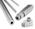
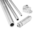
Fittings, Tubing & Nipples
Medium Pressure
Pressures to 20,000 psi (1379 bar)
Since 1945 Autoclave Engineers has designed and built premium quality valves, fittings and tubing. This commitment to engineering and manufacturing excellence has earned Autoclave a reputation for reliable, efficient product performance. Autoclave Engineers has long been established as the world leader in high pressure fluid handling components for the chemical/petrochemical, research, and oil and gas industries.
Medium Pressure Fittings, Tubing and Nipples Features:
.
Coned-and-Threaded Connection.
.
Available sizes are 1/4, 3/8, 9/16, 3/4Ī▒, and 1Ī▒.
.
Fittings and tubing manufactured from cold worked
stainless steel.
.
Operating Temperatures from -423ĪŃF (-252ĪŃC) to 1200ĪŃF (649ĪŃC).
.
Anti-vibration connection components available.
.
All items available in special material.
The medium pressure series uses AutoclaveĪ»s medium pressure connection. This coned-andthreaded connection features orifice sizes to match the high flow characteristics of this series.
www.autoclaveengineers.com
Medium Pressure Fittings
Pressures to 20,000 psi (1379 bar)
Autoclave Engineers medium pressure fittings, Series SF, are designed for use with Series 20SM medium pressure valves and Autoclave medium pressure tubing. They incorporate medium pressure coned-and-threaded connections with orifices sized to match the high-flow Series 20SC valves.
Connection Components
All Autoclave valves and fittings are supplied complete with appropriate glands and collars. To order these components separately, use order numbers listed. When using plug, collar is not required.
Gland
Plug
Collar
CGLX ( )
CPX ( )
CCLX ( )
Add tube size ( ) Example: To ensure proper fit use Autoclave Engineers tubing.
1/4Ī▒ - 40 1/4Ī▒ Gland - CGLX 40
3/8Ī▒ - 60 Note: Special material glands may be supplied with four flats
9/16Ī▒ - 90 in place of standard hex.
3/4Ī▒ - 120
1Ī▒ - 160
Elbow
CLX4400 SF250CX 1/4 20,000 0.125 1.12 1.50 0.38 0.50 0.75 0.75 0.62
(6.35) (1378.93) (3.18) (28.45) (38.10) (9.65) (12.70) (19.05) (19.05) (15.75) See
CLX6600 SF375CX 3/8 (9.53) 20,000 (1378.93) 0.219 (5.56) 1.38 (35.05) 2.00 (50.80) 0.44 (11.10) 0.62 (15.75) 1.00 (25.40) 1.00 (25.40) 0.75 (19.05)
CLX9900 SF562CX 9/16 20,000 0.359 1.75 2.50 0.53 0.94 1.25 1.25 1.00
(14.29) (1378.93) (9.12) (44.45) (63.50) (13.46) (23.88) (31.75) (31.75) (25.40) Figure 1
CLX12 SF750CX 3/4 20,000 0.516 2.25 3.00 0.62 1.19 1.50 1.50 1.38
(19.05) (1378.93) (13.11) (57.15) (76.20) (15.75) (30.23) (38.10) (38.10) (34.93)
CLX16 SF1000CX 1 20,000 0.688 3.00 4.12 0.72 1.38 2.06 2.06 1.75
(25.40) (1378.93) (17.48) (76.20) (104.65) (18.29) (35.05) (52.32) (52.32) (44.45)
For mounting hole option add suffix PM to catalog number. of any component.
*Maximum pressure rating is based on the lowest rating
Consult factory for mounting hole dimensions. Actual working pressure may be determined by tubing pressure rating, if lower.
All dimensions for reference only and subject to change. For prompt service, Autoclave stocks select products. Consult your local representative.
Tee
CTX4440 SF250CX 1/4 20,000 0.125 1.12 1.50 0.38 0.50 0.75 0.75 0.62
(6.35) (1378.93) (3.18) (28.45) (38.10) (9.65) (12.70) (19.05) (19.05) (15.75) See
CTX6660 SF375CX 3/8 (9.53) 20,000 (1378.93) 0.219 (5.56) 1.38 (35.05) 2.00 (50.80) 0.44 (11.10) 0.62 (15.75) 1.00 (25.40) 1.00 (25.40) 0.75 (19.05)
CTX9990 SF562CX 9/16 20,000 0.359 1.75 2.50 0.53 0.94 1.25 1.25 1.00
(14.29) (1378.93) (9.12) (44.45) (63.50) (13.46) (23.88) (31.75) (31.75) (25.40) Figure 2
CTX12 SF750CX 3/4 20,000 0.516 2.25 3.00 0.62 1.19 1.50 1.50 1.38
(19.05) (1378.93) (13.11) (57.15) (76.20) (15.75) (30.23) (38.10) (38.10) (34.93)
CTX16 SF1000CX 1 20,000 0.688 3.00 4.12 0.72 1.38 2.06 2.06 1.75
(25.40) (1378.93) (17.48) (76.20) (104.65) (18.29) (35.05) (52.32) (52.32) (44.45)
Cross
CXX4444 SF250CX 1/4 20,000 0.125 1.50 1.50 0.38 0.50 0.75 0.75 0.62
(6.35) (1378.93) (3.18) (38.10) (38.10) (9.65) (12.70) (19.05) (19.05) (15.75)
CXX6666 SF375CX 3/8 20,000 0.219 2.00 2.00 0.44 0.62 1.00 1.00 0.75
(9.53) (1378.93) (5.56) (50.80) (50.80) (11.10) (15.75) (25.40) (25.40) (19.05) See
CXX9999 SF562CX 9/16 20,000 0.359 2.50 2.50 0.53 0.94 1.25 1.25 1.00
(14.29) (1378.93) (9.12) (63.50) (63.50) (13.46) (23.88) (31.75) (31.75) (25.40) Figure 3
CXX12 SF750CX 3/4 20,000 0.516 3.00 3.00 0.62 1.19 1.50 1.50 1.38
(19.05) (1378.93) (13.11) (76.20) (76.20) (15.75) (30.23) (38.10) (38.10) (34.93)
CXX16 SF1000CX 1 20,000 0.688 4.12 4.12 0.72 1.38 2.06 2.06 1.75
(25.40) (1378.93) (17.48) (104.65) (104.65) (18.29) (35.05) (52.32) (52.32) (44.45)
*Maximum pressure rating is based on the lowest rating of any component. For mounting hole option add suffix PM to catalog number.
Actual working pressure may be determined by tubing pressure rating,Consult factory for mounting hole dimensions.
if lower.
All dimensions for reference only and subject to change. Figure 2
For prompt service, Autoclave stocks select products.
Consult your local representative.
Tee
Straight Coupling / Union Coupling
20FX4466 SF250CX 1/4 20,000 0.125 0.62 1.62 0.38 0.50 Straight
20UFX4466 (6.35) (1378.93) (3.18) (15.75) (41.15) (9.65) (12.70) Union
20FX6666 SF375CX 3/8 20,000 0.219 0.75 1.75 0.44 0.62 Straight
20UFX6666 (9.53) (1378.93) (5.56) (19.05) (44.45) (11.10) (15.75) Union See Figure 4
20FX9966 20UFX9966 SF562CX 9/16 (14.29) 20,000 (1378.93) 0.359 (9.12) 1.00 (25.40) 2.12 (53.85) 0.53 (13.46) 0.94 (23.88) Straight Union
20FX12 SF750CX 3/4 20,000 0.516 1.38 2.50 0.62 1.19 Straight
20UFX12 (19.05) (1378.93) (13.11) (35.05) (63.50) (15.75) (30.23) Union
20FX16 SF1000CX 1 20,000 0.688 1.75 3.50 0.72 1.38 Straight
20UFX16 (25.40) (1378.93) (17.48) (44.45) (88.90) (18.29) (35.05) Union
Bulkhead Coupling
20BFX4466 SF250CX 1/4 20,000 0.125 0.81 1.88 0.38 0.50 0.53 1.00 0.38
(6.35) (1378.93) (3.18) (20.57) (47.75) (9.65) (12.70) (13.46) (25.40) (9.65) See
20BFX6666 SF375CX 3/8 (9.53) 20,000 (1378.93) 0.219 (5.56) 0.94 (23.88) 2.00 (50.80) 0.44 (11.10) 0.62 (15.75) 0.62 (15.75) 1.00 (25.40) 0.38 (9.65)
20BFX9966 SF562CX 9/16 20,000 0.359 1.12 2.38 0.53 0.94 0.78 1.38 0.38
(14.29) (1378.93) (9.12) (28.45) (60.45) (13.46) (23.88) (19.81) (35.05) (9.65) Figure 5
20BFX12 SF750CX 3/4 20,000 0.516 1.69 2.62 0.62 1.19 0.91 1.88 0.38
(19.05) (1378.93) (13.11) (42.93) (66.55) (15.75) (30.23) (23.11) (47.75) (9.65)
20BFX16 SF1000CX 1 20,000 0.688 1.94 3.50 0.72 1.38 1.50 2.21 0.38
(25.40) (1378.93) (17.48) (49.28) (88.90) (18.29) (35.05) (38.10) (56.13) (9.65)
*Maximum pressure rating is based on the lowest rating of any component. Union Couplings are designed with a removable seat insert
Actual working pressure may be determined by tubing pressure rating, if lower. allowing disassembly and tubing removal without the necessity
All dimensions for reference only and subject to change. of loosening other items in a line.
For prompt service, Autoclave stocks select products.
Consult your local representative.
Figure 4
Straight Coupling / Union Coupling
Medium Pressure Tubing
Pressures to 20,000 psi (1379 bar)
Autoclave Engineers offers a complete selection of austenetic, cold drawn stainless steel tubing designed to match the performance standards of Autoclave valves and fittings. Autoclave medium pressure tubing is manufactured specifically for high pressure applications requiring both strength and corrosion resistance. The tubing is furnished in random lengths between 20 feet (6 meters) and 27 feet (8.2 meters). The average is 24 feet (7.3 meters). Medium Pressure Tubing is available in five sizes and a variety of materials.
Inspection and Testing
Autoclave EngineerĪ»s medium pressure tubing is inspected to assure freedom from seams, laps, fissures or other flaws, as well as carburization or intergranular carbide precipitation. The outside and inside diameters of the tubing are subject to special inspection and are controlled within close tolerences to assure proper fit. Sample pieces of tube for each lot are tested to confirm mechanical properties. Hydrostatic testing is also performed on a statistical basis and is conducted at the working pressure of the tube. Autoclave will perform 100% hydrostatic testing at additional cost if desired.
Special Materials Tubing Tolerance
In addition to the type 316 and 304 stainless steel tubing listed Nominal Tubing Size Tolerance/Outside Diameter
in this section, Autoclave has limited stock of hard-to-obtain inches (mm) inches (mm)
shorter lengths of the following tubing materials:
Monel 400*, Inconel 600*, Titanium Grade 2*, Nickel 200*, 1/4 (6.35) .248/.243 (6.30/6.17)
Hastelloy C276* -(* Trademark names) 3/8 (9.53) .370/.365 (9.40/9.27)
Please consult factory for stock availabilty. 9/16 (14.27) 3/4 (19.05) .557/.552 (14.15/14.02) .745/.740 (18.92/18.80)
1 (25.40) .995/.990 (25.27/25.14)
Catalog Tube Fits Tube Size Inches (mm) Flow Working Pressure psi (bar)*
Number Material Connection Outside Inside Wall Area -325 to 100ĪŃF 200ĪŃF 400ĪŃF 600ĪŃF 800ĪŃF
Type Diameter Diameter Thickness in.2 (mm2) -198 to - 37.8ĪŃC 93ĪŃC 204ĪŃC 316ĪŃC 427ĪŃC
MS15-092 316SS SF250CX 1/4 0.109 0.070 0.009 20,000 (1378.93) 20,000 (1378.93) 19,250 (1327.22) 18,050 (1244.48) 16,800 (1158.30)
MS15-192 304SS (6.35) (2.77) (1.78) (5.81) 20,000 18,950 17,200 17,000 16,150
(1378.93) (1306.54) (1185.88) (1172.09) (1113.49)
MS15-093 316SS 20,000 20,000 19,250 18,050 16,800
SF375CX 3/8 0.203 0.086 0.032 (1378.93) (1378.93) (1327.22) (1244.48) (1158.30)
MS15-193 304SS (9.53) (5.16) (2.18) (20.65) 20,000 20,000 19,250 18,050 16,800
(1378.93) (1378.93) (1327.22) (1244.48) (1158.30)
MS15-085 316SS 20,000 20,000 19,250 18,050 16,800
SF562CX 9/16 0.312 0.125 0.076 (1378.93) (1378.93) (1327.22) (1244.48) (1158.30)
MS15-187 304SS (14.29) (7.92) (3.18) (49.03) 20,000 20,000 19,250 18,050 16,800
(1378.93) (1378.93) (1327.22) (1244.48) (1158.30)
MS15-097 316SS 10,000 10,000 9,600 9,100 8,450
SF562CX 9/16 0.359 0.101 0.101 (689.46) (689.46) (661.89) (627.41) (582.60)
MS15-194 304SS (14.29) (9.12) (2.57) (65.16) 10,000 9,450 8,600 8,500 8,050
(689.46) (651.54) (592.94) (586.05) (555.02)
MS15-095 316SS 0.438 0.156 0.151 20,000 20,000 19,250 18,050 16,800
SF750CX 3/4 (11.13) (3.96) (97.42) (1378.93) (1378.93) (1327.22) (1244.48) (1158.30)
MS15-098 316SS (19.05) 0.516 0.117 0.209 10,000 10,000 9,600 9,100 8,450
(13.11) (2.97) (134.84) (689.46) (689.46) (661.89) (627.41) (582.60)
MS15-096 316SS 0.562 0.219 0.248 20,000 20,000 19,250 18,050 16,800
SF1000CX 1 (14.27) (5.56) (160.00) (1378.93) (1378.93) (1327.22) (1244.48) (1158.30)
MS15-099 316SS (25.40) 0.688 0.156 0.371 10,000 10,000 9,600 9,100 8,450
(17.48) (3.96) (239.35) (689.46) (689.46) (661.89) (627.41) (582.60)
Note: Caution should be exercised in proper selection of Medium Pressure Tubing based on actual operating conditions. Two series available: 10,000 psi (690 bar) and 20,000 psi (1379 bar).
*Maximum pressure rating is based on the lowest rating of any component.
Actual working pressure may be determined by tubing pressure rating, if lower.
All dimensions for reference only and subject to change.
For prompt service, Autoclave stocks select products. Consult your local representative.
Medium Pressure Coned-and-Threaded Nipples
Pressures to 20,000 psi (1379 bar)
For rapid system make-up, Autoclave Engineers supplies precut, coned-and-threaded nipples in various sizes and lengths for Autoclave medium pressure valves and fittings.
Special lengths
In addition to the standard lengths listed in the table below, nipples are available in any custom length. Consult factory.
Materials
Catalog numbers in table refer to Type 316 Stainless steel. Optional materials available. Consult factory.
Catalog Number Fits Connection Type Tube Size inches (mm) Working Pressure at 100ĪŃF psi (bar)*
Nipple Length In (mm)
2.75Ī▒ 3.00Ī▒ 4.00Ī▒ 6.00Ī▒ 8.00Ī▒ 10.00Ī▒ 12.00Ī▒
(69.85) (76.20) (101.60) (152.40) (203.20) (254.00) (304.80) O.D. I.D.
CNX4402-316 CNX4403-316 CNX4404-316 CNX4406-316 CNX4408-316 CNX44010-316 CNX44012-316 SF250CX 1/4 (6.35) 0.109 (2.77) 20,000 (1378.93)
CNX6603-316 CNX6604-316 CNX6606-316 CNX6608-316 CNX66010-316 CNX66012-316 SF375CX 3/8 (9.53) 0.203 (5.16) 20,000 (1378.93)
CNX9904-316 CNX9906-316 CNX9908-316 CNX99010-316 CNX99012-316 SF562CX 9/16 (14.29) 0.312 (7.92) 20,000 (1378.93)
CNLX9904-316 CNLX9906-316 CNLX9908-316 CNLX99010-316 CNLX99012-316 SF562CX 9/16 (14.29) 0.359 (9.12) 10,000 (689.46)
CNX1206-316 CNX1208-316 CNX12010-316 CNX12012-316 SF750CX 3/4 (19.05) 0.438 (11.13) 20,000 (1378.93)
CNLX1206-316 CNLX1208-316 CNLX12010-316 CNLX12012-316 SF750CX 3/4 (19.05) 0.516 (13.11) 10,000 (689.46)
CNX1606-316 CNX1608-316 CNX16010-316 CNX16012-316 SF1000CX 1 (25.40) 0.562 (14.27) 20,000 (1378.93)
CNLX1606-316 CNLX1608-316 CNLX16010-316 CNLX16012-316 SF1000CX 1 (25.40) 0.688 (17.48) 10,000 (689.46)
Note: Caution should be exercised when selecting medium pressure nipples since two series are
available: 10,000 psi (690 bar) and 20,000 psi (1379 bar)
See medium pressure tubing section for pressures at various temperatures.
*Maximum pressure rating is based on the lowest rating of any component.
Actual working pressure may be determined by tubing pressure rating, if lower.
All dimensions for reference only and subject to change.
For prompt service, Autoclave stocks select products. Consult your local representative.
Medium Pressure Check Valves
Pressures to 20,000 (1379 bar)
O-Ring Check Valves
Ball Check Valves
Ball Type Excess Flow Valves
Provides unidirectional flow and tight shut-off for liquids and gas with high reliability. When differential drops below cracking pressure*, valve shuts off. (Not for use as relief valve.)
Materials: Body, cover, poppet: 316 Stainless Steel, Cover gland: Stainless Steel, Spring: 300 Series Stainless Steel, Standard O-ring: Viton, for operation to 500ĪŃ F (260ĪŃC). Buna-N or Teflon available for 250ĪŃF (121ĪŃC) or 400ĪŃF (204ĪŃC) respectively; specify when ordering.
*Cracking Pressure: 20 psi (1.38 bar) Ī└30%. Springs for higher cracking pressures (up to 100 psi (6.89 bar)) available on special order for O-ring style check valves only.
Prevents reverse flow where leak-tight shut-off is not mandatory. When differential drops below cracking pressure, valve closes. With all-metal components, valve can be used up to 1200ĪŃF (649ĪŃC). See Technical Information section for connection temperature limitations. (Not for use as a relief valve.)
Ball is cradled in floating poppet to assure positive, in-line seating without Ī░chatterĪ▒. Poppet is designed essentially for axial flow with minimum pressure drop.
Materials: Body, cover, poppet: 316 Stainless Steel, Cover gland: Stainless Steel, Ball, Spring: 300 Series Stainless Steel
Protects pressure gauges and pressure instrumentation from surges in flow or sudden venting in the event of line failure.
Materials: Body, cover, sleeve: Type 316 Stainless Steel, Ball: 300 Series Stainless Steel, Cover gland: Stainless Steel.
Vertical Installation: Since this type of check valve employs a non-spring loaded ball, valve MUST be installed in VERTICAL position with arrow on valve body pointing UP. (cover gland up).
Resetting Valve: Equalize the pressure across the ball. The ball will drop and reset automatically.
CAUTION: While testing has shown O-Rings to provide satisfactory service life, both cyclic and shelf life may vary widely with differing service conditions, properties of reactants, pressure and temperature cycling and age of the O-ring. FREQUENT INSPECTIONS SHOULD BE MADE to detect any deterioration, and O-rings replaced as required.
CAUTION: See Tubing section for proper selection of tubing. NOTE: For optional material see Needle Valve Options section.
NOTE: Special material check valves may be supplied with four flats in place of standard hex.
Medium Pressure Check Valves
Catalog Number Fits Connection Type Pressure Rating psi (bar)* Orifice inches (mm) Rated Cv Dimensions - inches (mm)
A B C D Typical Hex
O-Ring Check Valves
CXO4400 SF250CX 20,000 0.125 0.28 2.94 2.50 0.38 0.50 0.81
(1378.93) (3.18) (74.68) (63.50) (9.65) (12.70) (20.57) See
CXO6600 SF375CX 20,000 (1378.93) 0.218 (5.54) 0.84 3.12 (79.25) 2.62 (66.55) 0.47 (11.94) 0.62 (15.75) 1.00 (25.40)
CXO9900 SF562CX 20,000 0.359 2.30 4.18 3.50 0.53 0.94 1.38
(1378.93) (9.12) (106.17) (88.90) (13.46) (23.88) (35.05) Figure 1
CXO12 SF750CX 20,000 0.516 4.70 5.12 4.38 0.62 1.19 1.75
(1378.93) (13.11) (130.05) (111.25) (15.75) (30.23) (44.45)
CXO16 SF1000CX 20,000 0.688 7.40 6.50 5.62 0.72 1.38 2.12
(1378.93) (17.48) (165.10) (142.75) (18.29) (35.05) (53.85)
Ball Check Valves
CXB4400 SF250CX 20,000 0.125 0.28 2.94 2.50 0.38 0.50 0.81
(1378.93) (3.18) (74.68) (63.50) (9.65) (12.70) (20.57) See
CXB6600 SF375CX 20,000 (1378.93) 0.218 (5.54) 0.84 3.12 (79.25) 2.62 (66.55) 0.47 (11.94) 0.62 (15.75) 1.00 (25.40)
CXB9900 SF562CX 20,000 0.359 2.30 4.18 3.50 0.53 0.94 1.38
(1378.93) (9.12) (106.17) (88.90) (13.46) (23.88) (35.05) Figure 1
CXB12 SF750CX 20,000 0.516 4.70 5.12 4.38 0.62 1.19 1.75
(1378.93) (13.11) (130.05) (111.25) (15.75) (30.23) (44.45)
CXB16 SF1000CX 20,000 0.688 7.40 6.50 5.62 0.72 1.38 2.12
(1378.93) (17.48) (165.10) (142.75) (18.29) (35.05) (53.85)
Ball Type Excess Flow Valves
CXK4400 SF250CX 20,000 0.125 0.37. 2.94 2.50 0.38 0.50 0.81
(1378.93) (3.18) (74.68) (63.50) (9.65) (12.70) (20.57) See
CXK6600 SF375CX 20,000 (1378.93) 0.218 (5.54) 0.66. 3.12 (79.25) 2.62 (66.55) 0.47 (11.94) 0.62 (15.75) 1.00 (25.40)
CXK9900 SF562CX 20,000 0.359 .212. 4.18 3.50 0.53 0.94 1.38
(1378.93) (9.12) (106.17) (88.90) (13.46) (23.88) (35.05) Figure 1
CXK12 SF750CX 20,000 0.516 .368. 5.12 4.38 0.62 1.19 1.75
(1378.93) (13.11) (130.05) (111.25) (15.75) (30.23) (44.45)
CXK16 SF1000CX 20,000 0.688 .864. 6.50 5.62 0.72 1.38 2.12
(1378.93) (17.48) (165.10) (142.75) (18.29) (35.05) (53.85)
Note:
.-Check Flow - water, GPM
For flow rates using alternate fluids, consult Autoclave Engineers.
*Maximum pressure rating is based on the lowest rating of any component.
Actual working pressure may be determined by tubing pressure rating, if lower.
All dimensions for reference only and subject to change.
For prompt service, Autoclave stocks select products. Consult your local representative.
Medium Pressure Line Filters
Pressures to 20,000 psi (1379 bar) Dual-Disc Line Filters
Cup-Type Line Filters
Autoclave Engineers Dual-Disc Line Filters are utilized in
numerous industrial, chemical processing, aerospace,
nuclear and other applications. With the dual-disc design,
large contaminant particles are trapped by the upstream filter
element before they can reach and clog the smaller micron-
size downstream element. Filter elements can be easily
replaced.
Materials: Body: cold-worked Type 316 Stainless Steel, Filter
Elements: 300 Series Stainless Steel.
Filter Elements: Downstream/upstream micron size 35/65 is
standard. 5/10 or 10/35 also available when specified. Other
element combinations available on special order.
Autoclave Engineers High Flow Cup-Type Line Filters are
recommended in high pressure systems requiring both high
flow rates and maximum filter surface area. Widely used in
the industrial and chemical processing fields, the cup design
offers as much as six times the effective filter area as
compared to disc-type units. In addition, the filter elements
can be quickly and easily replaced.
Materials: Body and Cover: cold-worked Type 316 Stainless
Steel. Filter Element: 300 Series Stainless Steel.
Filter Elements: 300 Series Stainless Steel sintered cup.
Standard elements available in choice of 5, 35 or 65 micron
sizes.
NOTE: All filters furnished complete with connection components unless otherwise specified. All dimensions for reference only and subject to change.
For optional materials, see Needle Valve Options section
Autoclave Engineers disc and cup type filters are designed to filter small amounts of process particles. It is recommended that all fluids are thoroughly cleaned prior to entering the higher pressure system.
NOTE 1: Special material filters may be supplied with four flats in place of standard hex.
NOTE 2: Pressure differential not to exceed 1,000 psi (69 bar) in a flowing condition.
Catalog Number Pressure Rating psi (bar)* Orifice inches (mm) Micron Size** Connection Size and Type Effective Filter Element Area in.2 (mm2) Dimensions - inches (mm)
A B C D Typical Hex
Dual-Disc Line Filters
CLFX9900 20,000 0.312 35/65
(1378.93) (7.92) SF562CX 0.25 4.94 2.68 0.53 .94 1.38
CLFX9900-5/10 20,000 0.312 5/10
(1378.93) (7.92) (161.29) (125.48) (68.07) (13.46) (23.88) (35.05)
CLFX9900-10/35 20,000 0.312 10/35
(1378.93) (7.92)
Cup-Type Line Filters
CXF4-5 20,000 0.125 5 SF250CX 0.81 (522.57) 2.94 (74.68) 2.50 (63.50) 0.38 (9.65) .50 (12.70) 0.81 (20.57)
CXF4-35 (1378.93) (3.18) 35
CXF4-65 65
CXF6-5 20,000 0.218 5 SF375CX 0.81 (522.57) 3.12 (79.25) 2.62 (66.55) 0.47 (11.99) .62 (15.75) 1.00 (25.40)
CXF6-35 (1378.93) (5.54) 35
CXF6-65 65
CXF9-5 20,000 0.359 5 SF562CX 1.53 (987.09) 4.18 (106.17) 3.50 (88.90) 0.53 (13.46) .94 (23.88) 1.38 (35.05)
CXF9-35 (1378.93) (9.12) 35
CXF9-65 65
CXF16-5 5 SF1000CX 5.00 (3225.80) 6.62 (168.15) 5.75 (146.05) 0.72 (18.29) 1.38 (35.05) 2.12 (53.05)
CXF16-10 20,000 (1378.93) 0.688 (17.48) 10
35
CXF16-35
65
CXF16-65
Note:
**Other micron sizes available on special order. Change last digits of the catalog number
accordingly.
For optional materials, see Needle Valve Options section.
*Maximum pressure rating is based on the lowest rating of any component.
Actual working pressure may be determined by tubing pressure rating, if lower.
All dimensions for reference only and subject to change.
For prompt service, Autoclave stocks select products. Consult your local representative.
Dual-Disc Line Filters
Cup-Type Line Filters
Anti-Vibration Collet Gland Assembly
Pressures to 20,000 psi (1379 bar)
Series KCBGLX Sizes to 1Ī▒ (25.40 mm) For extreme conditions of vibration and/or shock in tubing systems, such as an unsupported line near a compressor, coned-and-threaded connections are offered with the Autoclave anti-vibration collet gland assembly. Completely interchangeable with standard Autoclave Engineers medium pressure connections, the collet gland assembly provides equally effective pressure handling capability.
In standard connection systems, the bending stresses on the threaded area of the tubing imposed by excessive vibration or movement may cause premature fatigue failure of the tubing at the back of the thread. By moving the stress concentration back to the unthreaded part of the tubing and providing a wedge-type gripping action, the Autocalve Engineers anti-vibration collet gland assembly strengthens the entire structure. With stress concentration reduced and overall stress level maintained well below the endurance limit of the material, the result is virtually unlimited vibrational fatigue life.
A less complex and more economical design than other vibration-resistant connections, the collet gland assembly utilizes the same coned-and-threaded features of Autoclave medium pressure connections. Series KCBGLX extends the gland nut to provide room for the tapered slotted collet. The design provides a slight difference in angles between the collet and the corresponding taper of the gland nut. As the nut is tightened, it acts to wedge the tapered end of the collet into a gripping engagement with the tubing.
Materials
Type 316 stainless steel with bonded dry film (316 MC) moly lubricant.
NOTE: Special material assemblies may be supplied with four flats in place of standard hex.
Catalog Number Part Outside Diameter Tubing Size in. (mm) Dimensions - inches (mm) Series KCBGLX 20,000 psi ( 1379 bar) Standard Autoclave Engineers collar not included in complete assembly A B Hex
A B Hex
KCBGLX40-316MC Complete assembly 1/4 (6.35) 0.94 (23.88) 1.19 (30.23) 0.62 (15.75)
KCBLX40-316MC Collet body
KCCLX40-316MC Slotted collet
KGLX40-316MC Gland nut
KCBGLX60-316MC Complete assembly 3/8 (9.53) 1.19 (30.23) 1.50 (38.10) 0.81 (20.63)
KCBLX60-316MC Collet body
KCCLX60-316MC Slotted collet
KGLX60-316MC Gland nut
KCBGLX90-316MC Complete assembly 9/16 (14.29) 1.41 (35.81) 1.78 (45.21) 0.94 (23.88)
KCBLX90-316MC Collet body
KCCLX90-316MC Slotted collet
KGLX90-316MC Gland nut
KCBGLX120-316MC Complete assembly 3/4 (19.05) 1.59 (40.37) 2.00 (50.80) 1.25 (31.75)
KCBLX120-316MC Collet body
KCCLX120-316MC Slotted collet
KGLX120-316MC Gland nut
KCBGLX160-316MC Complete assembly 1 (25.40) 1.69 (42.93) 2.38 (60.45) 1.50 (38.10)
KCBLX160-316MC Collet body
KCCLX160-316MC Slotted collet
KGLX160-316MC Gland nut |